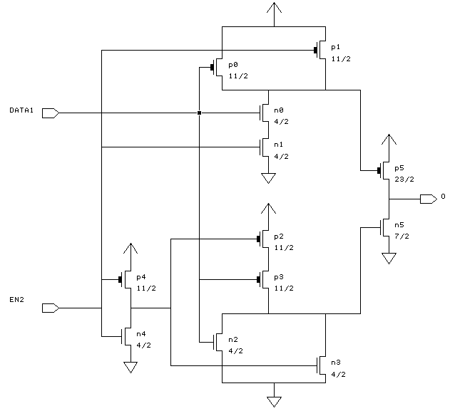
Buffer tri state inverting analog signal analysis resistor represented biasing amplifier self second using Logic gates Answered: below is the transistor schematic and circuit symb
transistors - How to made a Tri State Switch? - Electrical Engineering
Tri state buffer transistor schematic Tri state buffer transistor schematic Non-inverting tri-state buffer-switch demo circuit
Tri state logic buffer in verilog and tristate buffer testbench.
Buffer tristate tri truth logic inverterA.2.2.3 transmission gates, tri-state inverters, and buffers Logic gatesTri-state buffer.
How does tri-state buffers workTri state buffer transistor schematic Buffer inverting tri state tristate non circuit only inverter transistors possible output logic not cause putting front willTri state logic buffer in verilog and tristate buffer testbench..

Tri-state logic gate and application of tri state buffer ~ electronics
Buffer tristate schematic circuit circuitlab created using stackBuffer tri state using transistors schematic inverting non circuit possible only gates logic circuitlab created State tri logic table use truth buffers ands gatesDigital logic.
Tri-state buffer exampleMaking a bi-directional tri-state buffer using two normal tri-state State tri logic buffer gate enable gates implemented bus applicationTri state buffer transistor schematic.

Buffer state tri ppt powerpoint presentation skip video
Tri state buffer transistor schematicBuffer tristate schematic layout karmic standard cel Logic gatesWhat is tri-state buffer?.
Electronic – 3-state buffer mechanism – valuable tech notesƎxclusive architecture What is tri-state buffer?Tri state buffer schematic.
Buffer tri state schematic circuit mosfet
Tri ttl tristateKarmic 23: tristate buffer Logic gatesTri-state inverting buffer analog signal analysis.
Switch state tri made gate resistive gnd omega consider loadBuffer state tri using directional bi buffers normal making two schematic possible source Basic ttl tri-state buffer circuit examplesTri state buffer transistor schematic.

Cs150 unit 10 page 3
Electronic – implementing a cmos tristate inverter – valuable tech notesTri state buffer transistor schematic State tri buffer non inverting transistors only ttl possible schematic cannot npn output chips used soTri state buffer schematic.
.

What is Tri-State Buffer? | How it Works? - Semiconductor Club

digital logic - Tristate buffer - Electrical Engineering Stack Exchange

ƎXCLUSIVE ARCHITECTURE

Tri State Buffer Transistor Schematic

transistors - How to made a Tri State Switch? - Electrical Engineering

Tri State Buffer Schematic

Tri State Buffer Schematic